Control Board V1!
Goodbye sketchy electronics…
Hello printed circuit board!
For a long time I’d been wanting to make a printed circuit board both to be able to have a cool setup for a project but also to learn how it’s actually done. Every microcontroller, breakout board and shield I have is a PCB (of course), and I’ve learned to really respect them. They’re clean, last a long time, and usually look cool! Adafruit does this well… look at the silkscreen on this board… it looks amazing!
Anyway, for my board I needed to implement a few things. First, my robot needs 12 PWM outputs for each motor which must be supplied by the teensy (which will be on the PCB via headers). To keep everything clean, it makes sense that there is also a 6V power supply on the board to allow the PCB to act as a power distribution board and supply a control signal. To accomplish this, I decided to use a 10A external power supply connected to a 3s Lipo.
With that, I’d be able to drive the motors and the PCB would be able to suit my most basic needs. But I had some more wishes:
- Motor power shutoff capability driven by the teensy
- Inertial measurment unit
- Battery capacity guage
- On-board LoRA radio
Let’s start with the power shutoff ability. During my one-leg testing period (which you can read about starting here), I noticed that when the servos weren’t speicifically commanded to a certain position, which usually happens during new uploads to the teensy, they would go to random positions! This was a huge issue for me because the motors would often try to go somewhere that they physically couldn’t as a result of the hardware constraints of the robot. The reason for this is that the servo data line is floating when I don’t command a position to the servos, and this can be fixed with a pullup/pulldown resistor. However, I thought it would be cooler to use a relay that activates when a high signal is sent from the teensy. Upon upload or a loss of power to the teensy (in which case the servo data lines would be floating) the teensy signal line will go low (no power to the teensy!). The advantage is that I can also manually turn the motors on/off, so if I detect an error while walking that may cause damage to the robot (or something like that), I can automatically shut everything off. Plus, having a relay is much cooler.
Next, and IMU! I selected the LSM6DSOX acceleromter and gyroscope because it is very accurate and can easily interface to the teensy via I2C protocol. To test it, I first ordered a breakout board for it from Adafruit, and later I used their design to validate my interfacing with the chip. Fast forward 1 week, I finished building the board and successfully tested the chip. I’m planning on using this library to fuse the IMU data to get euler angle that I can use to determine the robot’s direction.
Kind of an extra… a battery capacity guage! I decided to put a 1s lipo on the robot just to power the teensy and its peripherals like the LSM6DSOX. I’d always thought that measuring the capacity of a battery was interesting, since you can’t really go by its voltage. Plus, it’s just the kind of gimmick I like. I found a breakout board for the LC709203F battery guage on adafruit that I tested and I eventually decided to stick it on my PCB. Fast forward 1 week this thing works perfectly! My teensy was able to interface with it via I2C right away… perfect!
Finally, and on-board LoRA radio. After I got an RFM69HCW radio breakout board (again from Adafruit), I was really attracted to the idea of using for the robot since it had really, really long range (tested it up to approxiamately 100m) and stability. I was able to use the breakout board well, but unfortunately, I found an error after making the board… the motors seemed to be affected whenever two radios were communicating (on motor was connected to an MCU with a radio). This was a total let down, and I’m still trying to find the issue.
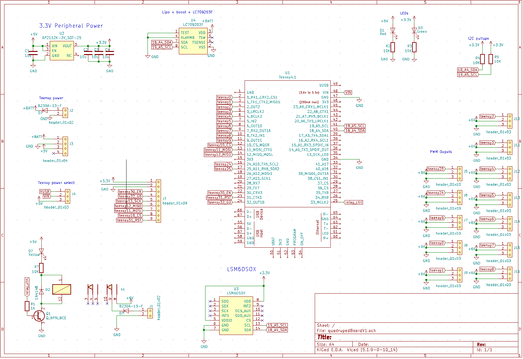
All in all, here is the final schematic:
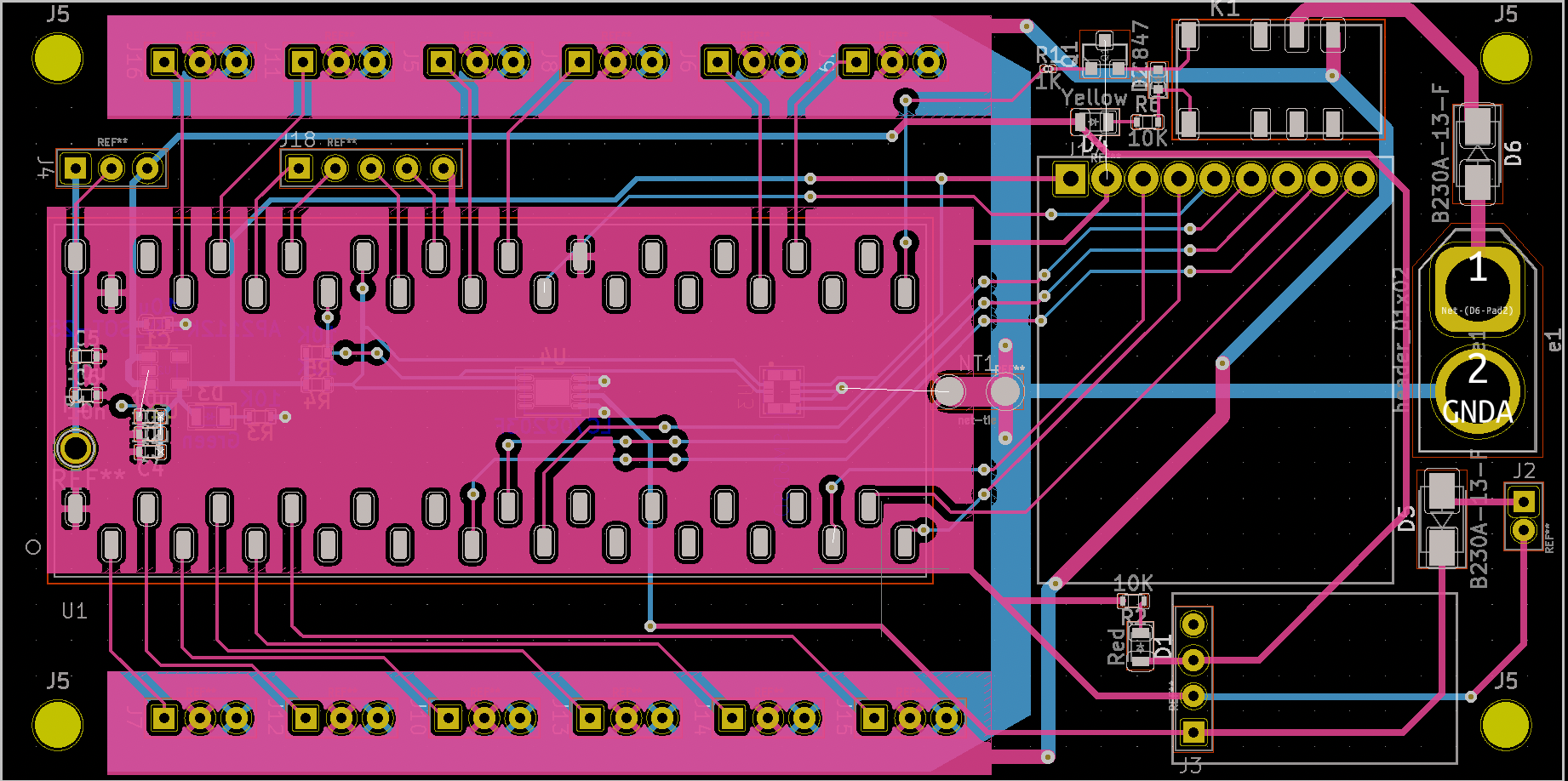
And the layout:
I’m really please with this board. It was my first, and despite making many mistakes (see the section below), I learned a lot and it was a lot of fun. Additionally, it works for what it was supposed to, controlling the motors, which means that I can continue on with the project and complete the building of the robot.
Problems, so far:
Problems? Oh, there are no problems… :D
- Motor header holes (through hole) too small
- Silkscreen for XT-60 connector flipped
- Poor silkscreen design for chip “1” pins
- Rows of smd female headers for the teensy are too far apart from each other
- LoRA header pins are flipped (mirrored)
- Miniboost header pins are flipped (mirrored)
- The LSM6DSOX I2C address is incorrect… it is using one that must be manually selected (but still works)
But… what I had the greatest fear for, the chips and the relay, work flawlessly!
