Complementary Filters for IMU Fusion
Let’s fuse sensors - simply!
Why do I need a filter?
One of the hardest problems to solve in robotics is how to get orientation data accurately. Most IMUs don’t return their orientation directly in euler angles. Gyroscopes, for example, actually measure the velocity of a rotation. Additionally, gyroscopes and accelerometer data need to be corrected to compensate for noise or unexpected movement. Here’s an overview of things that need to be fixed:
Accelerometers are fast and don’t drift, but they are very noisy. To counteract this noise, you need to use a low-pass filter, typically an aggressive one, which will result in a smoother (but slower to react) output signal. Additionally, accelerometers become inaccurate when they are tilted and moving translationally at the same time and when they are subject to sudden bumps or taps.
Gyroscopes, on the other hand, has very few of these problems. They are less noisy, less affected by changes in weather, and
faster, since they don’t require a filter. Roll and pitch angles calculated from gyroscopes are actually the integral of the
output signal, however, which means that minuscule noise in the signal will eventually multiply to skew the calculated rotation
angle. In other words, gyroscopes drift.
Thus, it makes sense to choose a filter that combines the two sensors: since gyroscopes are nearly perfect, by inputing a little bit of the calculated accelerometer data into the gyro output, the gyroscope’s drift can be compensated.
Which filter, then? There are a multitude of solutions, including the Kalman filter, a complex and time-consuming algorithm that’s a little overkill for this application. Instead, a complementary filter can be used, which is much less complex and faster too.
Here’s the equation:
\(\Theta_{n}\) = \(α \cdot \left ( \Theta_{n-1} + g \cdot \Delta t \right ) + \left ( 1 - α \right ) \cdot a\)
g is the raw gyroscope data in radians per second (or degrees per second) and
a is the rotation angle calculated from the accelerometer data.
\(a_{pitch} = \tan^{-1}(\frac{-accel_{x}}{(accel_{y}^{2} + accel_{z}^{2})^{1/2}})\) \(a_{roll} = \tan^{-1}(\frac{accel_{y}}{(accel_{z}^{2} + accel_{z}^{2})^{1/2}})\)
Here’s the code:
float pitchFromAccel = 0;
float rollFromAccel  = 0;

pitchFromAccel = atan(-accelerometer.x / sqrt(pow(accelerometer.y, 2) + pow(accelerometer.z, 2)));
rollFromAccel = atan(accelerometer.y / sqrt(pow(accelerometer.x, 2) + pow(accelerometer.z, 2)));
// rollFromAccel = atan2(accelerometer.y, accelerometer.z);

// Complimentary Filter
_pitch = (_pitchGyroFavoring) * (_pitch + (gyroscope.y * (1.00 / _filterUpdateRate))) + (1.00 - _pitchGyroFavoring) * (pitchFromAccel);
_roll = (_rollGyroFavoring) * (_roll + (gyroscope.x * (1.00 / _filterUpdateRate))) + (1.00 - _rollGyroFavoring) * (rollFromAccel);

// The above code returns the angle in RADIANS
Essentially, the filter allows you to determine each sensor’s contribution to the overall calculated angle by setting the percent contribution of each. Since the sum of the percent contributions must equal 100% (1), however, all you need to do is determine the gyroscope’s contribution and the complement to that will be used to determine the accelerometer’s contribution.
The best part about this filter is that it is super fast and easy to understand/troubleshoot!
So how does this really work compared to other filtering methods?
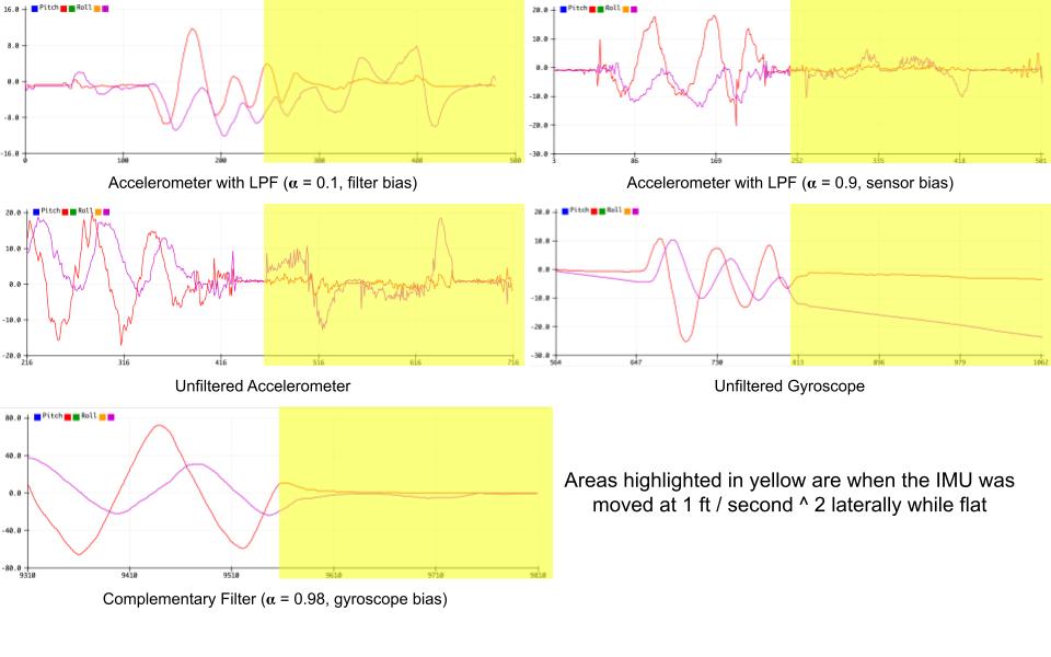
Let’s analyze the data. The unfiltered accelerometer is plagued with noise, as expected, however it always stays accurate (on average, close to the true value). It’s precision can be improved with a low pass filter, which reduces noise, however it also results in calculated data that is slow to react to sudden changes… it lags. The alternative is to use a weak filter (the graph in the top-right) that places bias on incoming data instead. This, however, results in poor noise reduction.
Enough with the accelerometer, how about the gyroscope? Since this sensor is more precise than the accelerometer, it doesn’t need to be directly filtered. The measurement drifts, however, as a result of minor measurement errors building up in the integral.
Also notice the difference between the areas shaded in yellow (where I accelerated the sensor forwards and backwards at 1 ft/second) between the accelerometer and the gyroscope. The accelerometer is immensely affect and becomes innaccurate (I kept the sensor level at [0,0] the entire time). The gyroscope is unaffected, which makes sense.
Finally, it can be seen that the complementary filter is like the gyro, however it doesn’t drift! This makes sense because I placed a 98% bias on the gyroscope data but only a 2% bias on the accelerometer (just enough to remove the drift). And the data is only barely influenced by the lateral acceleration.
To make it easy to integrate this filter into your projects, I created an approved third-party arduino library that implements it called SimpleFusion. Download it from github or install it in the arduino IDE if you are interested! (You can also find download instructions on ArduBadge)
Problems… so far
I haven’t found any! I’ve done extensive testing on my library and it works quite well so far. If you use my library and find any problems, please submit an issue on the library’s github. I’ll be happy to consider any changes or fixes!
